LiDAR Services
Overview
Utilizing LiDAR technology, the system ensures real-time obstacle detection and emergency stops during robot movement through high-precision environmental perception and instantaneous data processing.
The service employs the Livox Mid-360 LiDAR sensor, a cost-effective and reliable laser rangefinder featuring:
- Detection range: 0.1m (min) to 100m (max)
- Non-repetitive scanning pattern for enhanced detail resolution
- Robust optical/structural design adaptable to various industrial scenarios
- Supports mapping, localization, recognition, and obstacle avoidance functions
LiDAR Service Architecture
- Livox-SDK Layer
- Acquires raw measurement data via serial port from Livox Mid-360 hardware
- Parses data packets into point cloud format
- Unilidar Node Layer
- Receives parsed point cloud data through Unilidar SDK
- Localization Module
- Processes point clouds with localization maps and IMU/Odometry data
- Gets robot coordinate transformations via sensor fusion
- Planning & Control Module
- Generates motion commands based on localization data and robot state

Lidar Configuration
Dimensions & Mechanical Layout
The physical dimensions and mounting hole specifications of the Livox Mid-360 are shown in the following diagram:

The IS robot is equipped with two Livox Mid-360 LiDAR units (front and rear), arranged as shown in the following diagram:

Field of View (FOV) Specifications
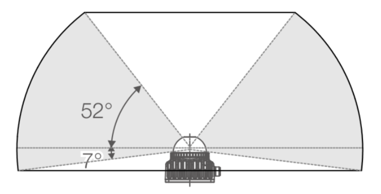
As illustrated in the FOV diagram below, the Mid-360 features:
- Horizontal FOV: 360° (full coverage)
- Vertical FOV: Up to 59°
Effective Range Characteristics:
The operational range varies across different FOV zones:
- Upper Vertical FOV: Shorter effective range
- Lower Vertical FOV: Longer effective range
| FOV | |
|---|---|
 |  |
| Horizontal FOV | Vertical FOV |
Point Cloud Coordinate System
The Cartesian coordinate system O-XYZ of the Livox Mid-360 is defined as follows:
- Point O serves as the origin
- O-XYZ constitutes the point cloud coordinate frame
- The directions of each axis are illustrated in the accompanying diagram
struct Point {
    float x;  // meters
    float y;  // meters
    float z;  // meters
    float intensity;
};
Point Cloud Data
By default, the Mid-360 starts outputting point cloud data immediately upon power-up. The data includes:
- Timestamp
- Target reflectivity
- Coordinate information (Cartesian
(x, y, z)or Spherical(r, θ, φ)) - Tagging information
Coordinate Systems & Conversion
The Mid-360 supports both Cartesian (x, y, z) and Spherical (r, θ, φ) coordinate representations. The relationship between these systems is illustrated in the diagram below:
Special Cases:
- If no object is detected or the object is beyond the measurement range (e.g., >100 m):
- Cartesian output:
(0, 0, 0) - Spherical output:
(0, θ, φ)(retains angular information but ranger = 0)
- Cartesian output:

Upon startup, the IS robotic dog automatically initializes the LiDAR system and publishes the point cloud data to the DDS topic. The figures below display raw point clouds captured by the front and rear LiDARs in different scenarios, viewed from near and far perspectives.

