LiDAR Service
Overview
Based on LiDAR (laser radar) equipment, through high-precision environmental perception and real-time data processing, to ensure that the robot in the process of movement in a timely manner to detect obstacles to achieve stop barrier function.
The LiDAR used by LiDAR service is Livox Mid-360, which is a cost-effective, safe and reliable laser detection rangefinder sensor. It can detect objects with a nearest distance of 0.1 meters and a farthest distance of 100 meters. It adopts clever and reliable optical and structural design to realize non-repetitive scanning, can detect richer details, adapt to different application scenarios, and can support mapping, positioning, identification, industrial realization of functions such as obstacle avoidance.
The following figure shows the system architecture of the LiDAR service.
- The Livox-SDK obtains the raw measurement data packet from the Livox Mid-360 hardware through the serial port and parses it into point cloud data.
- The Unilidar Node module uses the Unilidar SDK to obtain the parsed point cloud data.
- The positioning module receives point cloud data, positioning map and IMU / Odom data, and obtains the robot coordinate transformation relationship through sensor fusion.
- The planning and control module solves the control instructions based on the positioning information and the robot state information, and finally controls the robot motion.
Lidar Configuration
Size and Layout
The size of Livox Mid-360 and the size of mounting holes are shown in the figure below.

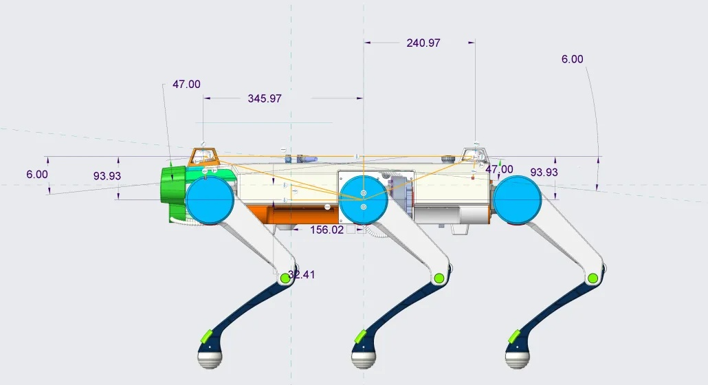
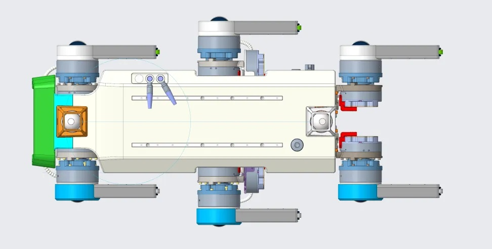
The IS robot IS equipped with two Livox Mid-360 front and rear radars, and their layout positions are shown in the following figure.
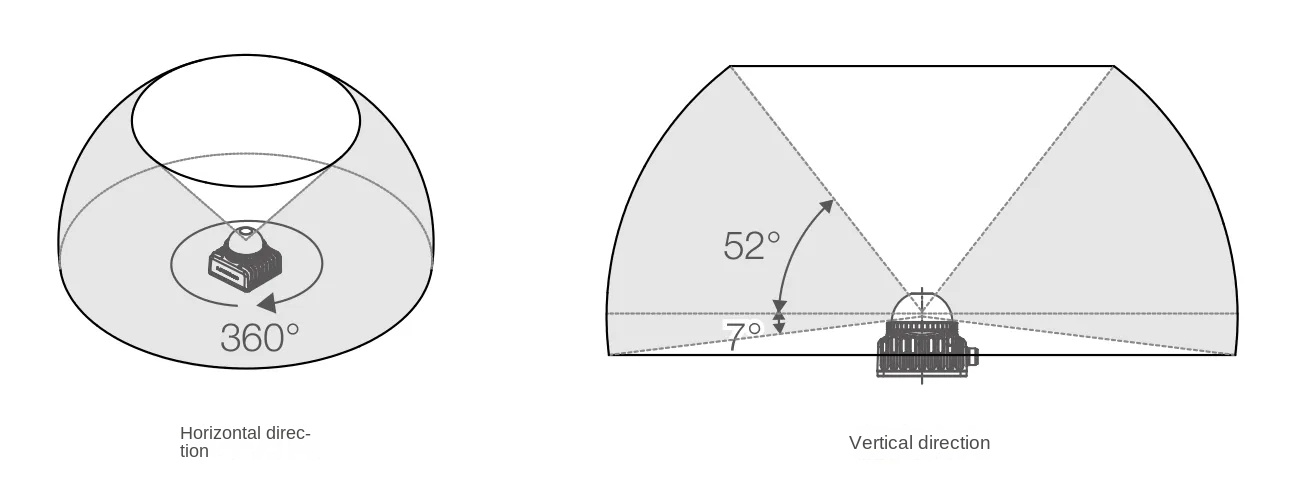
Effective Field of View (FOV) Range
The FOV range of Mid-360 is shown in the following figure. The horizontal range is 360 ° and the vertical maximum is 59 °. The effective range is different in different FOV regions: in the vertical FOV range, the shorter the effective range is closer to the upper side, and the longer the effective range is closer to the lower side.
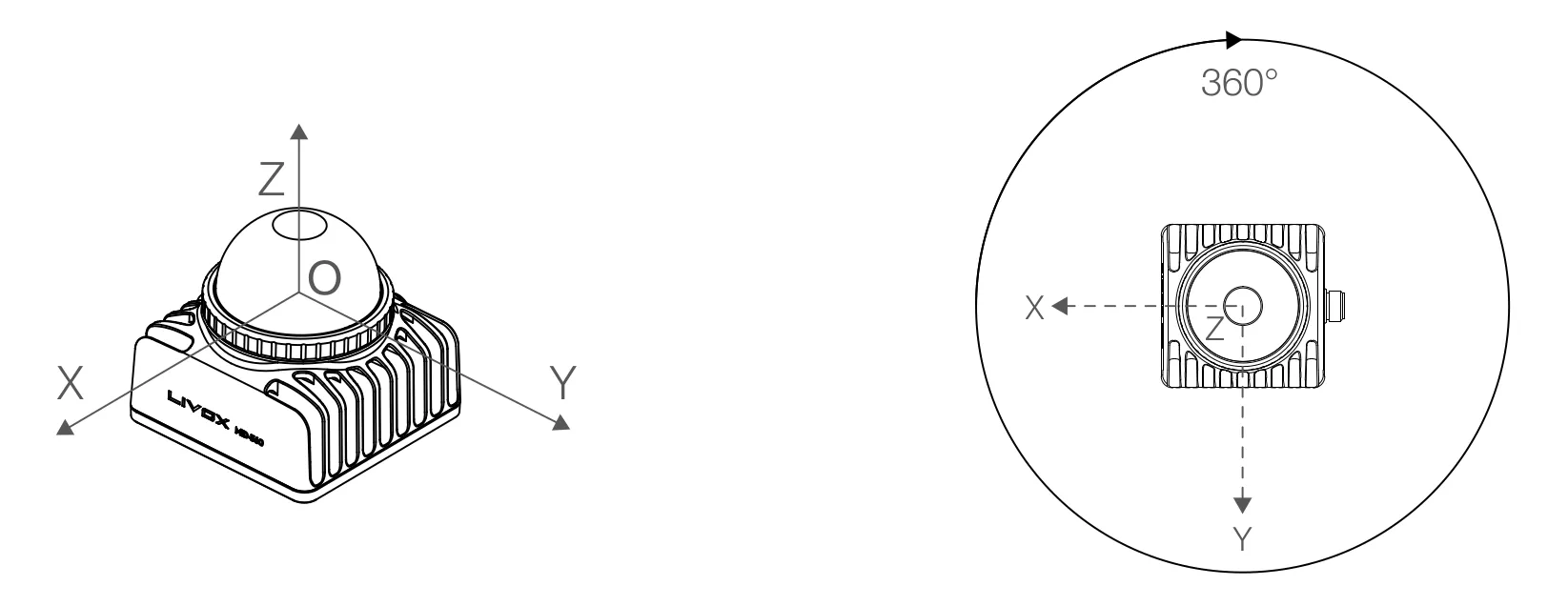
Point Cloud Coordinate System
The definition of the rectangular coordinate O-XYZ of Livox Mid-360 is as follows: point O is the origin, O-XYZ is its point cloud coordinate system, and the direction of each coordinate axis is shown in the figure.
Point Cloud Data
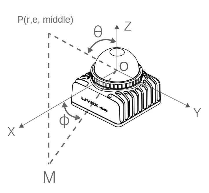
By default, Mid-360 starts to output point cloud data after being powered on. The point cloud data includes time stamp, target reflectivity, seat marking information and marking information. Among them, the coordinate information of Mid-360 can be expressed as rectangular coordinate system (x, y, z) or spherical coordinate system (r, θ, φ). The corresponding relationship between rectangular coordinate and spherical coordinate is shown in the following figure. The coordinate conversion relationship can be described as follows:
If there is no detected object ahead or the detected object exceeds the range (e. G.> 100 m), the point cloud output is ; In the spherical coordinate system, the point cloud output is .
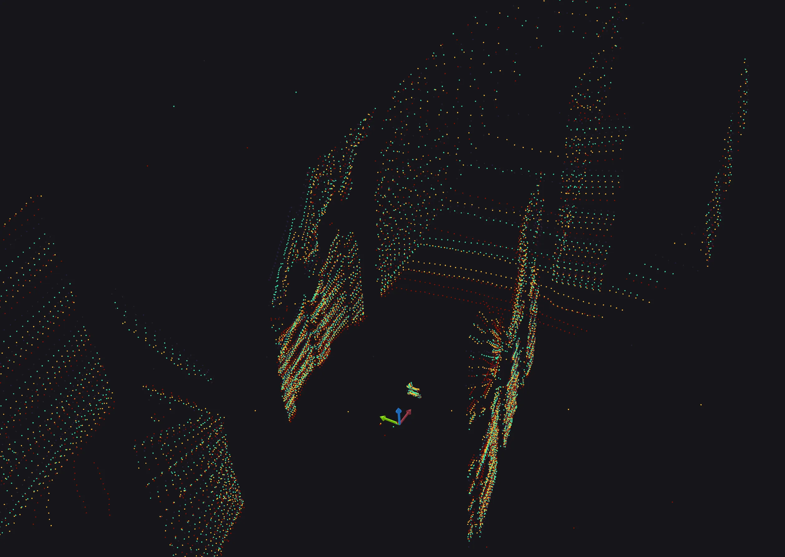
The IS robot dog opens the opportunity to automatically start the relevant programs of the laser radar and publishes the point cloud collected by the laser radar to the DDS topic. The following figure shows the original point clouds collected by the front and back radars of IS observed from near and far perspectives in different scenes.